

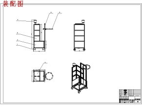
装配图A0
液压传动机械手的设计
摘要本次设计的液压传动机械手根据规定的动作顺序,综合运用所学的基本理论、基本知识和相关的机械设计专业知识,完成对机械手的设计,并绘制必要装配图、液压系统图、PLC控制系统原理图。机械手的机械结构采用油缸、螺杆、导向筒等机械器件组成;在液压传动机构中,机械手的手臂伸缩采用伸缩油缸,手腕回转采用回转油缸,立柱的转动采用齿条油缸,机械手的升降采用升降油缸,立柱的横移采用横向移动油缸;在PLC控制回路中,采用的PLC类型为FX2N,当按下连续启动后,PLC按指定的程序,通过控制电磁阀的开关来控制机械手进行相应的动作循环,当按下连续停止按钮后,机械手在完成一个动作循环后停止运动。
本设计拟开发的上料机械手可在空间抓放物体,动作灵活多样,可代替人工在高温和危险的作业区进行作业,可抓取重量较大的工件。
关键词机械手、液压、控制回路、PLC
The design of the hydraulic manipulator
Abstract The design of hydraulic drive manipulator movements under the provisions of the order, use the basic theory, basic knowledge and related mechanical design expertise comprehensively to complete the design,and drawing the necessary assembly, hydraulic system map, PLC control system diagram. Manipulator mechanical structure using tanks, screw,guide tubes and other mechanical device component;In the hydraulic drive bodies,manipulator arm stretching using telescopic tank,rotating column of tanks used rack,manipulator movements using tank movements,the column takes the horizontal movement of tanks;The PLC control circuit use the type of FX2N PLC.When pressed for commencement,PLC in accordancewith the prescribed procedures,through the control of the solenoidvalve to control the switch manipulator corresponding moves cycle,after press the row stop button, the manipulator complete a cycle of action to stop after the hole campaign.
The design of the proposed development of the information on the manipulator can grasp up in space objects,flexible andvaried movements,can replace the artificial heat and dangerous operation conducted operations,and can grasp the largerworkpieces.
Keywords Manipulator、Hydraulic、Control Loop、PLC
目录
摘要1
1前言3
1.1工业机器人简介3
1.2世界机器人的发展3
1.3我国工业机器人的发展4
1.4我要设计的机械手5
1.4.1臂力的确定5
1.4.3确定运动速度6
1.4.4手臂的配置形式6
1.4.5位置检测装置的选择7
1.4.6驱动与控制方式的选择7
2手部结构8
2.1概述8
2.2设计时应考虑的几个问题8
2.3驱动力的计算9
2.4两支点回转式钳爪的定位误差的分析11
3腕部的结构12
3.1概述12
3.2腕部的结构形式12
3.3手腕驱动力矩的计算13
4臂部的结构15
4.1概述15
4.2手臂直线运动机构16
4.2.1手臂伸缩运动16
4.2.2导向装置17
4.2.3手臂的升降运动18
4.3手臂回转运动19
4.4手臂的横向移动19
4.5臂部运动驱动力计算20
4.5.1臂水平伸缩运动驱动力的计算20
4.5.2臂垂直升降运动驱动力的计算21
4.5.3臂部回转运动驱动力矩的计算21
5液压系统的设计23
5.1液压系统简介23
5.2液压系统的组成23
5.3机械手液压系统的控制回路23
5.3.1压力控制回路23
5.3.2速度控制回路24
5.3.3方向控制回路25
5.4机械手的液压传动系统25
5.4.1上料机械手的动作顺序25
5.4.2自动上料机械手液压系统原理介绍26
5.5机械手液压系统的简单计算29
5.5.1双作用单杆活塞油缸29
5.5.2无杆活塞油缸(亦称齿条活塞油缸) 32
5.5.3单叶片回转油缸33
5.5.4油泵的选择35
5.5.5确定油泵电动机功率N 36
6 PLC控制回路的设计37
6.1电磁铁动作顺序37
6.2现场器件与PLC内部继电器对照表38
6.3 PLC与现场器件的实际连接图39
6.4梯形图41
6.5指令程序42
7结束语47
8参考文献48
9致谢50
翻译文献51

PLC连接图A2

活塞杆A2

手臂升降机构图A1

手部结构图A1

液压回路图A1

2摘要

3设计所包含文件

4设计参数

5目录

1字数


")


