ВІВц
еЊвЊ
зЈгУМаОпЪЧЭЈгУМаОпЁЂзщКЯМаОпвдМАЫцааМаОпжаЕФвЛжжЁЃзЈгУМаОпвђСуМўЭтаЮЦцЬиЃЌБфЕФВЛФмЛђШБЁЃзЈгУМаОпдкЯждкЕФЩњВњКЭЩшМЦжаЃЌЦфЕиЮЛЗЧГЃжЎживЊЃЌвђЖјЃЌЖдЦфНјаабаОПЗЧГЃгавтвхЁЃ
БОДЮЩшМЦЕФСуМўЪЧВІВцЃЌВІВцЪЧЦћГЕБфЫйЯфЩЯЕФВПМўЃЌгыБфЫйЪжБњЯрСЌЃЌЮЛгкЪжБњЯТЖЫЃЌВІЖЏжаМфБфЫйТжЃЌЪЙЪфШы/ЪфГізЊЫйБШИФБфЁЃВІВцжївЊЪЧгУдкВйзнЛњЙЙжаЃЌБШШчИФБфГЕДВЛЌвЦГнТжЕФЮЛжУЃЌЪЕЯжБфЫйЃЛЛђепгІгУгкПижЦРыКЯЦїЕФФіКЯЖЯПЊЕФЛњЙЙжаЃЌДгЖјПижЦКсЯђЛђзнЯђНјИјЁЃ
ЩшМЦФкШнАќРЈЛњаЕМгЙЄЙЄвеКЭзЈгУМаОпЩшМЦЁЃМгЙЄЙЄвеЩшМЦАќРЈСуМўЕФЙЄвеЗжЮіЃЌВФСЯЕФбЁдёЃЌЩњВњХњСПЕФШЗЖЈЃЌМгЙЄЙЄвеТЗЯпМАЙЄађПЈЕФЩшМЦЕШЁЃБОДЮзЈгУМаОпЩшМЦЯГ73гвЖЫУцЃЌЩшМЦФкШнАќРЈЖЈЮЛЁЂМаНєдЊМўМАЗНАИЃЌМаОпЬхЃЌЖдЕЖзАжУЕШЁЃ
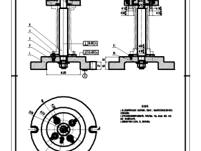
ЙиМќДЪЃКВІВцЁЂЛњаЕМгЙЄЙЄвеЁЂзЈгУМаОпЁЂЯГ73гвЖЫУц
Abstract
Special fixtures are one of the common fixtures, combination fixtures, and pallets. Special fixtures are indispensable because of the strange shape of the parts. Special fixtures arevery important in their current production and design, so it makes sense to study them.
The design part is a fork. The fork is a component on the car's gearbox. It is connected to the shifting handle and is located at the lower end of the handle. The intermediate shiftingwheel is toggled to change the input/output speed ratio. The shift fork is mainly used in the operating mechanism, such as changing the position of the lathe slip gear to achieve shifting, or in a mechanism for controlling the engagement and disconnection of the clutch, thereby controlling lateral or longitudinal feed.
The design includes machining processes and special fixture designs. The process design includes the process analysis of the parts, the selection of materials, the determination of the production batch, the processing route and the design of the process card. This special fixture design and milling 73 right end face, the design content includes positioning, clamping components and solutions, clip specific, tool setting device.
Keywords: fork, machining process, special fixture, milling 73 right end
ФПТМ
еЊвЊI
Abstract II
ЕквЛеТаїТл1
1.1ЛњДВМаОпЕФЗжРрМАИХЪі1
1.2ЛњДВдкЛњаЕМгЙЄжаЕФзїгУ2
ЕкЖўеТСуМўНсЙЙМАМгЙЄЗжЮіЁЂШЗЖЈЩњВњРраЭМАжЦдьаЮЪН4
2.1СуМўНсЙЙМАМгЙЄЗжЮі4
2.1.1СуМўзїгУЕФЗжЮі4
2.1.2СуМўВФСЯЕФЗжЮі4
2.1.2СуМўзщГЩБэУцЕФЗжЮі5
2.1.3СуМўМгЙЄБэУцЕФЗжЮі5
2.1.4СуМўаЮЮЛЙЋВюЕФЗжЮі6
2.2ШЗЖЈСуМўЕФЩњВњРраЭ6
2.3ШЗЖЈСуМўЕФжЦдьаЮЪН6
ЕкШ§еТСуМўМгЙЄЙЄвеЕФЩшМЦгыМЦЫу8
3.1ЛљзМЕФбЁдё8
3.1.1ДжЛљзМЕФбЁдё8
3.1.2ДжЛљзМЕФбЁдё8
3.2бЁдёЁЂБШНЯКЭШЗЖЈМгЙЄЙЄвеТЗЯп8
3.2.1бЁдёМгЙЄЙЄвеТЗЯп8
3.2.2БШНЯКЭШЗЖЈМгЙЄЙЄвеТЗЯп9
3.3ШЗЖЈЛњДВЁЂМаОпЁЂЕЖОпМАСПОп9
3.4ШЗЖЈСуМўЕФЛњМгЙЄгрСП10
3.5ШЗЖЈЧаЯїгУСПЁЂМЦЫуМгЙЄЙЄЪБ12
ЕкЫФеТзЈгУМаОпЕФЩшМЦ30
4.1ЖЈЮЛЗНАИКЭдЊМўЕФШЗЖЈгыбЁдё30
4.1.1ЖЈЮЛЗНАИЕФШЗЖЈ30
4.1.2ЖЈЮЛдЊМўЕФбЁдё30
4.2МаНєЗНАИКЭдЊМўЕФШЗЖЈгыбЁдё30
4.2.1МаНєЗНАИЕФШЗЖЈ30
4.2.2МаНєдЊМўЕФбЁдё31
4.3ЩшМЦМаОпЬх31
4.4бЁдёЖдЕЖзАжУ31
4.5МЦЫуЯГЯїСІМАМаНєСІ32
4.6ЗжЮіЖЈЮЛЮѓВю32
НсТл33
жТаЛ34
ВЮПМЮФЯз35

ВІВцСуМўЭМA4

МаОпзАХфЭМA0

ВІВцУЋХїЭМA4

ЖЈЮЛПщA2

ЖЈЮЛзљA3

ЖдЕЖзљA3

МаОпЬхA1

VаЭбЙАхA3

Й§ГЬПЈ

МаОпЩшМЦВПЗж

ЩшМЦЫљАќКЌЮФМў

зжЪ§ЭГМЦ

ЙЄађПЈ

ЫЕУїЪщЧАШ§вГ
ЩъУїЃКФкШнРДздгУЛЇЩЯДЋЃЌжјзїШЈЙщдзїепЫљгаЃЌШчЩцМАЧжШЈЮЪЬтЃЌЧыгыЮвУЧСЊЯЕЃЌЮвУЧНЋМАЪБДІРэЃЁ